10+ fft block diagram
Its the basic unit consisting of just two inputs and two outputs. This operation is useful in many fields but computing it directly from the definition is often too slow to be practical.
![]()
Fourier Transform Infrared Spectroscopy Wikiwand
First here is the simplest butterfly.

. In the signal flow diagram in Fig. This algorithm is applied. FFT As a result we have seen that the breaking up a large DFT into two smaller DFTs will allow savings in computations.
A small sometimes not so small P. The FFT allows signal gain adjustment in a fixed-point environment by using a block representation of input values of block size N to an N-point FFT. Fourier analysis converts a signal from its original domain often time or space to a representation in the frequency domain and vice versa.
The Butterfly Diagram is the FFT algorithm represented as a diagram. The DFT is obtained by decomposing a sequence of values into components of different frequencies. Now - some explanation for each picture.
This process is demonstrated by the block diagram below. FFT transforms signals from the time domain to the frequency domain. Fast Fourier transform FFT and inverse FFT IFFT are the fundamental algorithms at the heart of optical orthogonal frequency division multiplexing OOFDM transceivers.
FFT block diagram 2-point DFT 2-point DFT 2-point DFT 2-point DFT Merge two 2-point DFTs Merge two 2-point DFTs Merge two 4-point DFTs. 1 the basic butterfly block does two type of basic operations viz addition. A fast Fourier transform FFT is an algorithm that computes the discrete Fourier transform DFT of a sequence or its inverse IDFT.
1 Typical FFT diagram. Architecture of the FFT Block. If the signal level is too high then clipping and distortion.
2277-9655 Mehrotra et al. Aynchronous top level block diagram The top-level block diagram of the Asynchronous version of the FFT4 design is as given in above figure. RIT Computer Engineering Senior Design Project Winter 2005-2006 Aaron Swerdlin Brian Hamilton Ibe Owunwanne.
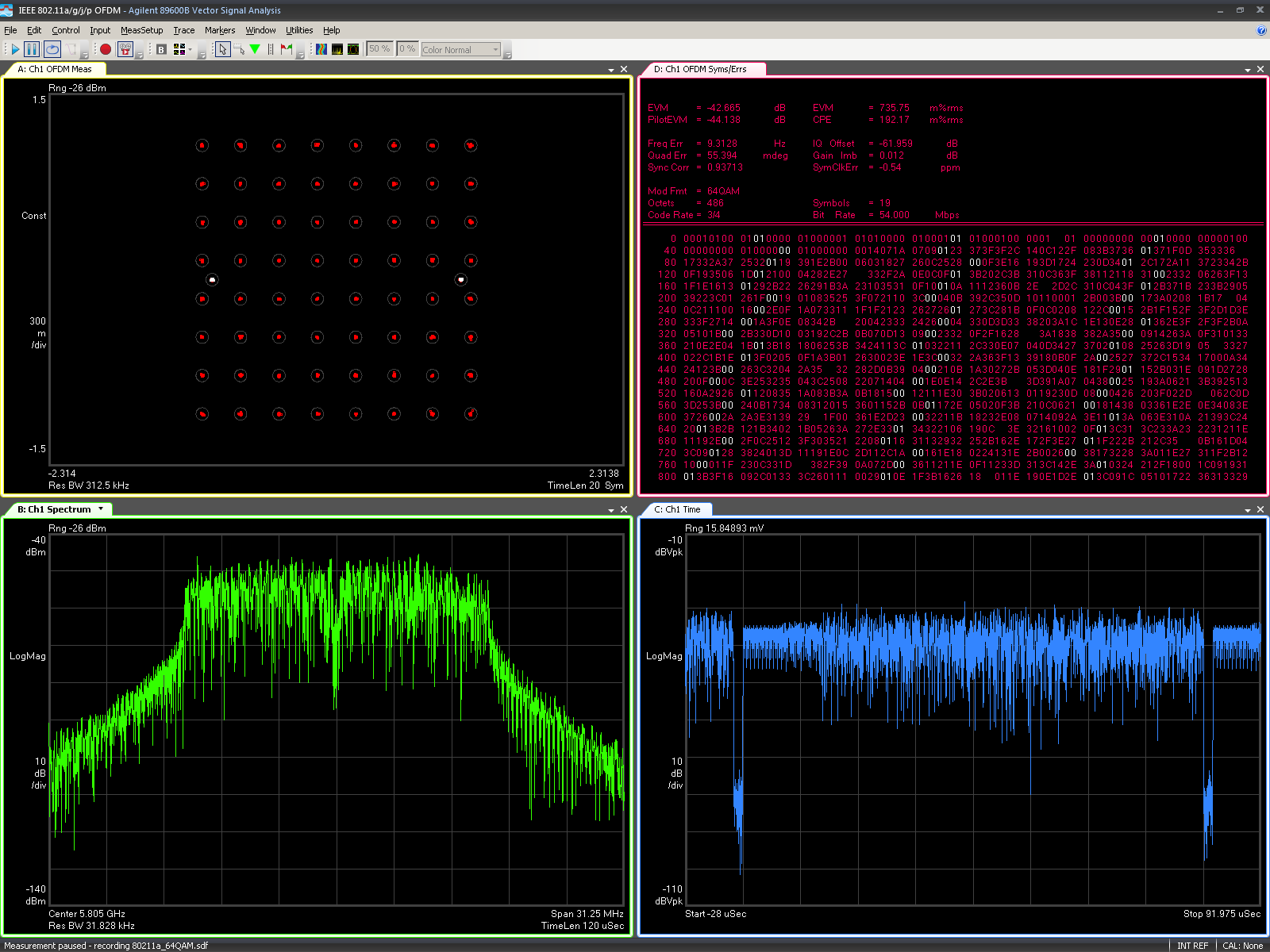
Base frequency component represents the test signal 1KHz sine wave - set to 0db. FFT analysis is one of the most used techniques when performing signal analysis across several application domains. The FFT analyzer requires attenuators of gain stages to ensure that the signal is at the right level for the analogue to digital conversion.
102 Questions With Answers In Fast Fourier Transform Science Topic
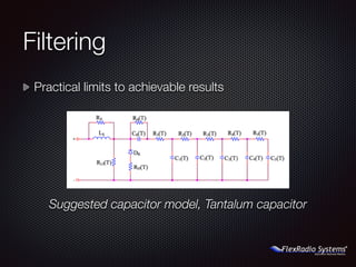
N5ac 2015 Huntsville Hamfest Flexradio Systems

What Is A D Converter How To Wire It
Proposed Transceiver Block Diagram With Shaded Area Showing The Scope Download Scientific Diagram

Digital Signal Processing Complete Guide With Examples
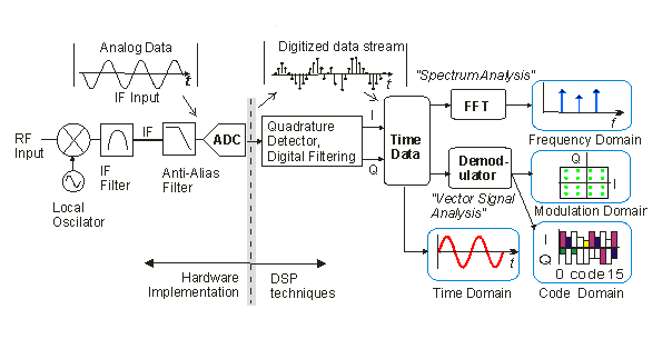
Vector Signal Analyzer Wikiwand

Advanced Video Coding Wikiwand

102 Questions With Answers In Fast Fourier Transform Science Topic

Methodology Spisim Eda For Signal Integrity Power Integrity And Circuit Simulation
Vector Signal Analyzer Wikiwand
Why Does A Sinusoidal Signal In The Time Domain Have Two Frequency Responses In The Frequency Domain Quora
2

Vector Signal Analyzer Wikiwand
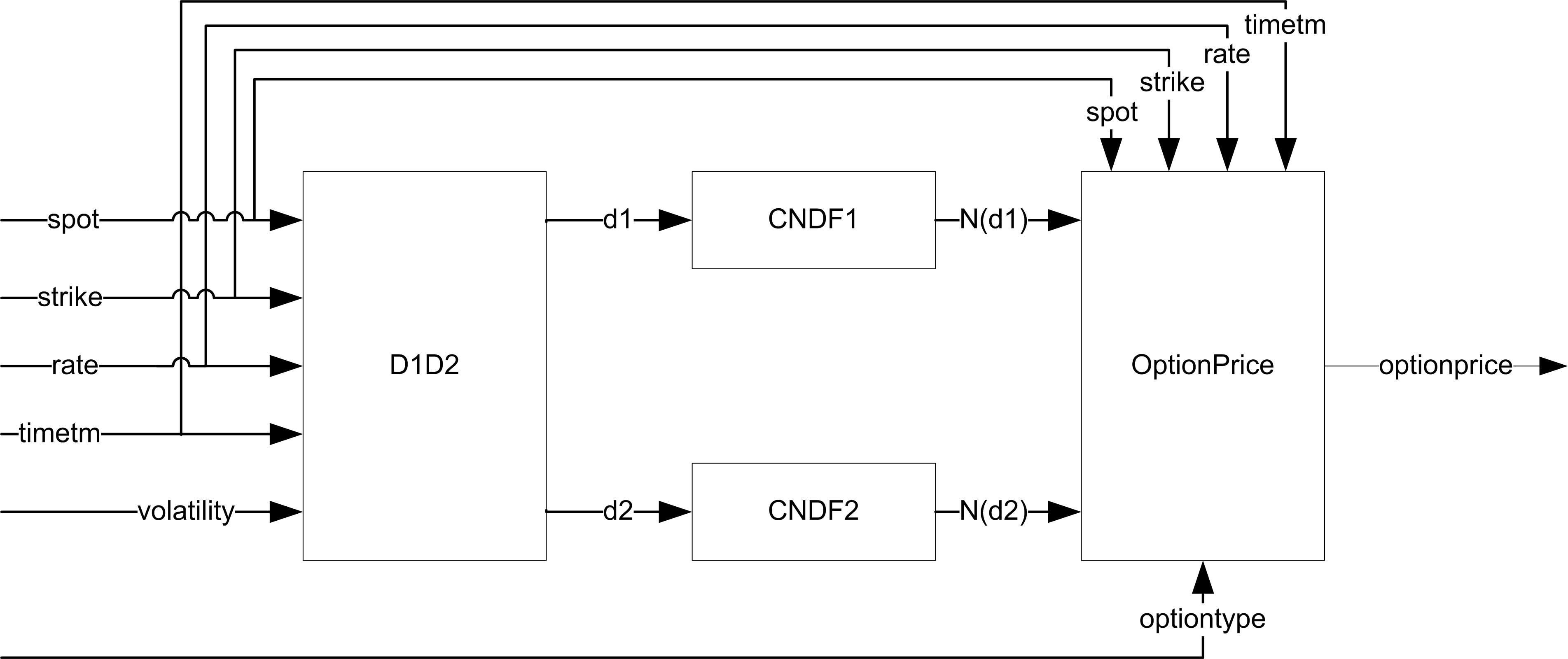
Black Scholes In Hardware

102 Questions With Answers In Fast Fourier Transform Science Topic

Fourier Transform Infrared Spectroscopy Wikiwand

Telecommunications